TM 11-6625-3081-23
5-14. OPTICAL SIGNAL ANALYZER FILTER AND DETECTOR ASSEMBLY 2A1A1A14 REPAIR
5-14
This task covers replacement of:
Para
Item
Para
Item
1. Relay K1
3. Switch S1 or S2
2.
Resistor R5
4.
Optical switch A1 or A3
INITIAL SETUP
Personnel Required
Tools
Goggles
Heat gun
Materials (appendix C)
Rubber gloves (Item 26)
Lens paper (Item 36)
Nose-mouth shield (Item 42)
Solder (Item 43)
Masking tape (Item 45)
39B ATE Repairer
Equipment Condition
OSA disassembled (para 5-13)
FOLLOWUP
OSA reassembly (para 5-13)
Applicable Configuration
E/O Bench Serial No. 00001 thru
00105
1. RELAY K1 REPLACEMENT
REMOVAL
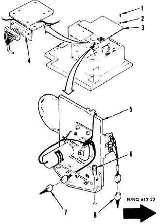
a.
Remove 16 screws (1) and washers
(2), position baffle cover (3),
disconnect W14P1 from A3J1 (4)
and remove baffle cover to allow
removal of filter and detector
assembly (5).
CAUTION
Exercise special care when working
near optical surfaces.
Avoid touch-
ing or contaminating any optical
surface.
b.
c.
5-68
Cover all exposed optics in fil-
ter and detector assembly with
lens paper and masking tape. If
any optical surfaces need clean-
ing refer to paragraph 2-22.
Remove three screws (6).
Change 4