TM 11-6625-3081-23
5-15, OPTICAL SIGNAL ANALYZER PHOTOMULTIPLIER AND BRACKET ASSEMBLY
5-15
2A1A1A7 REPAIR
This task covers replacement of:
Para
Item
Para
Item
1. Shutter
3. Temperature sensor Q1
2. Optical switch A1 or A2
4. Resistors R1 through R4
INITIAL SETUP
Tools
Goggles
Heat gun
Materials (appendix C)
Epoxy adhesive (Item 2)
Silicone rubber (Item 3)
Applicator (Item 6)
Cheesecloth pad (Item 11)
Rubber gloves (Item 26)
Heat shrinkable tubing (Item 30)
Lens paper (Item 36)
Nose-mouth shield (Item 42)
Solder (Item 43)
Lacing tape (Item 44)
Masking tape (Item 45)
Trichlorotrifluoroethane (Item 47)
Personnel Required
39B ATE Repairer
One assistant
Equipment Condition
OSA disassembled (para 5-13)
(not required for para3)
FOLLOWUP
Reassemble OSA (para 5-13)
(not required for para 3)
Applicable Configuration
E/O Bench Serial No. 00001 thru
00105
1. SHUTTER REPLACEMENT
REMOVAL
a.
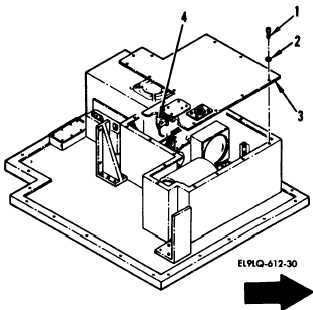
Remove 16 screws (1) and washers
(2), position baffle cover (3)
and disconnect connector W14P1
from connector A3J1 (4).
CAUTION
Exercise special care when working
near optical surfaces.
Avoid touch-
ing or contaminating any optical
surfaces in optical signal analyzer.
b. Cover exposed optics with lens
paper and secure with masking
tape.
Change 4
5-73