TM 11-6625-3081-23
5-14. OPTICAL SIGNAL ANALYZER FILTER AND DETECTOR ASSEMBLY 2A1A1A14
5-14
REPAIR (cont)
2. RESISTOR R5 REPLACEMENT
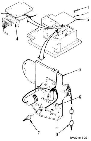
REMOVAL
a.
Remove 16 screws (1) and washers
(2) and position baffle cover
(3), disconnect W14P1 from A3J1
(4) and remove baffle cover to
allow removal of filter and
detector assembly (5).
b. Remove three screws (6).
c.
Cut lacing tape and disconnect
the following connectors:
A14P1 from W14J3 (7)
A14P2 from W14J2 (8)
d.
Remove filter and detector assem-
bly (5) and place on workbench.
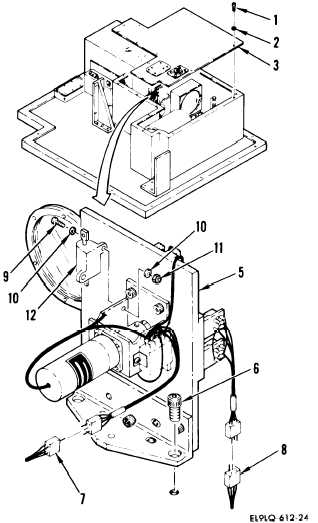
e.
Remove two screws (9), four wash-
ers (10), and two nuts (11).
f.
Tag and remove leads from
defective resistor R5 (12).
INSTALLATION
g.
Install in reverse order of
removal.
END OF TASK
5-70