TM 11-6625-3081-23
5-14. OPTICAL SIGNAL ANALYZER FILTER AND DETECTOR ASSEMBLY 2A1A1A14
5-14
REPAIR (cont)
4. OPTICAL SWITCH A1 OR A3 REPLACEMENT
NOTE
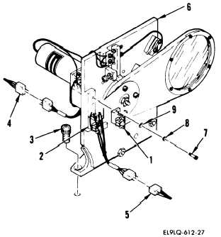
This procedure is used to replace
optical switch A1 (1) or A3 (2).
REMOVAL
a.
Refer to 3 above and do steps a
and b.
b. Remove three screws (3).
c.
Cut lacing tape and disconnect
the following connectors:
A14P1 from W14J3 (4)
A14P2 from W14J2 (5)
d.
Remove filter and detector assem-
bly (6) and place on workbench.
e.
Remove two screws (7), lockwash-
ers (8), washers (9), and optical
switch (l).
f.
Tag and remove leads from optical
switch.
INSTALLATION
g.
Install in reverse order of
removal.
END OF TASK
5-72