TM 11-6625-3081-23
4-5. BLOWER ASSEMBLY 1A6 0R 1A12 REPA1R (cont)
4-5
INSTALLATION
o.
p.
q.
r.
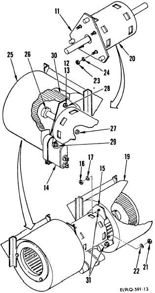
Using reference lines marked
during disassembly, position left
bracket (11) on motor (20) and
secure with four lockwashers (24)
and nuts (23).
Position motor/left bracket as-
sembly on the left blower fan
housing (25) motor mount screws
(27, 28, and 29).
Install a lockwasher (13) and nut
(12) on motor mount screws (27
and 28).
Install capacitor assembly (14),
lockwasher- (13), and nut (12) on
motor mount screw (29).
NOTE
Ensure set screw is secured on flat
surface of motor shaft.
s.
t.
u.
Center fan blade (30) on motor
shaft and, using a balldriver
tool, tighten set screw (26).
Position right bracket (15) to
motor and secure with four lock-
washers (22) and nuts (21).
Position right blower fan housing
(19) and motor mount screws (31)
on motor/right bracket assembly
and secure with three lockwashers
(17) and nuts (16).
4-12