TM 11-6625-3081-23
5-12. OPTICAL SIGNAL ANALYZER (OSA) HOUSING ASSEMBLY REPAIR (cont)
5-12.
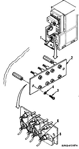
5. RESISTOR REPLACEMENT
REM0VAL
a. On OSA, open access door (1).
b. On resistor assembly TB3 (2),
remove two screws (3) and
lockwashers (4).
c. Cut lacing tape as necessary to
access TB3.
d. Unsolder resistor leads (5) from
terminal posts (6). Remove
resistor.
INSTALLATION
e. Install resistor in reverse order
of removal.
Locator Chart - TB 3
Resistor
R1
R2
R3
R4
R5
R6
R7
R8
From
E1
E1
E3
E3
E5
E5
E7
E7
To
E2
E3
E4
E4
E6
E7
E8
E8
END OF TASK
5-58