TM 11-6625-3081-23
5-11. OPTICAL SIGNAL ANALYZER (OSA) ASSEMBLY 2A1A1 REPLACEMENT (cont)
5-11
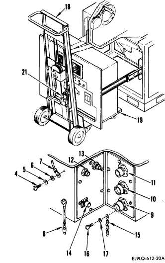
17. Install chain (15) with screw (16)
and washer (17).
18. On lower left corner of OSA, connect
the following connectors:
W31P1 to J1O (9)
W35P4 to J11 (10)
W32P3 to J12 (11)
W34P2 to J14 (13)
W34P1 to J13 (12)
W36P1 to J15 (14)
19. Connect quick disconnect ground
lead (8).
20. Prepare surface and hardware (4 thru
7) for application of zinc chromate
primer (para 2-19).
21. Install ground lead E4 (7) on OSA
with screw (4), lockwasher (5), and
two washers (6).
22. Apply zinc chromate primer to surface
and hardware (4 thru 7).
23.
24.
END
Remove ratchet strap (21) and remove
chassis lift (18) and lumber (19).
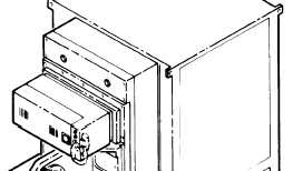
DO NOT USE FINGERS TO UNLOCK SLIDES.
USE SCREWDRIVER TO PREVENT INJURY.
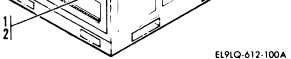
Push OSA into dayside test bench and
install 12 screws (1) and washers
(2).
OF TASK
5-54