TM 11-6625-3081-23
5-13. OPTICAL SIGNAL ANALYZER (OSA) ASSEMBLY 2A1A1 REPAIR
5-13
This task covers OSA disassembly and OSA reassembly
INTIAL SETUP
Equipment Condition
Tools/Special Tools
OSA removed (para 5-11)
Chassis lift
FOLLOWUP
Materials (appendix C)
OSA installation (para 5-11)
Lumber 4 x 4 x 36 inch (2) (Item 32)
Lens paper (Item 36)
Applicable Configuration
Lacing tape (Item 44)
E/O Bench Serial No. 00001 thru
Masking tape (Item 45)
00105
Personnel Required
396 ATE Repairer
Three assistants
DISASSEMBLY
1.
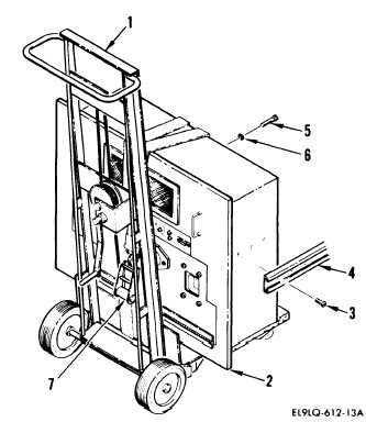
Push chassis lift (1) with OSA (2) to
open area of floor.
Lock wheels on
chassis lift.
There should be enough
area on floor to lay OSA on its
back.
2.
Remove 12 screws (3) and two slide
assemblies (4) from OSA.
CAUTION
Four corner screws must be left in
place or OSA will be damaged when
lowered onto its back.
3.
Remove 16 screws (5) and washers (6)
from rear of OSA.
Leave four corner
screws in place.
4..
Remove ratchet strap (7).
Change 4
5-59