TM 11-6625-3081-23
5-19. OPTICAL SIGNAL ANALYZER (OSA) RELAY ASSEMBLY 2A1A1A12 REPAIR
5-19
This task covers replacement of:
Para
Item
Para
Item
1. Relays K1 through K4
3.
Resistor R1
2. Diodes CR1 through CR4
INITIAL SETUP
Personnel Required
Tools
39B ATE Repairer
Contact installation/removal tool
Heat gun
Materials (appendix C)
Heat shrinkable tubing (Item 29)
Solder (Item 43)
Lacing tape (Item 44)
Masking tape (Item 45)
Equipment Condition
Power removed (para 2-24.1)
Applicable Configuration
E/O Bench Serial No. 00001 thru
00105
1. RELAYS K1 THROUGH K4 REPLACEMENT
NOTE
This procedure is used to replace
any of four relays.
REMOVAL
a.
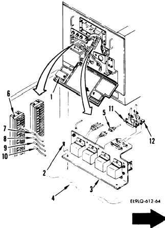
Open access door (1).
b.
Remove two screws (2) securing
relay assembly (3) to mounting
plate assembly (4).
c.
Cut lacing tape and disconnect
connector A12J3 from connector
W11P7 (5).
d.
On terminal block TB1 (6), remove
terminal leads E3 (7), from TBl-
140, E4 from TB1-11D (8), E5 from
TB1-12K (9), and E6 from TB1-10G
(10) using contact installation/
removal tool.
e.
Disconnect the following
connectors:
W2P2 from A12J1 (11)
W4P2 from A12J2 (12)
f.
Remove relay assembly (3) from
OSA and place on workbench.
Change 4
5-93


