TM 11-6625-3081-23
5-32.
OPTICAL SIGNAL GENERATOR (OSG) ASSEMBLY 2A2A3 REPAIR
5-32
This task covers replacement of:
Para
Item
Para
Item
1.
OSG cover
3. Lamp sensor A2
2.
Lamp A2DS1
4.
Relay bracket assembly A1,
K1 through K3
INITIAL SETUP
Tools/Special Tools
Personnel Required
396 ATE Repairer
7/64 hex head ball end wrench
Equipment Conditions
Materials (appendix C)
Lens paper (Item 36)
Solder (Item 43)
Lacing tape (Item 44)
Masking tape (Item 45)
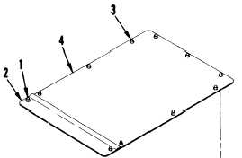
1. OSG COVER REPLACEMENT
NOTE
This procedure can be used when
access to OSG is required for
maintenance.
REMOVAL
a.
Loosen two captive fasteners (1)
and remove forward cover (2).
b.
Loosen nine captive fasteners (3)
and remove rear cover (4).
CAUTION
Avoid touching or contaminating
optical surfaces.
c.
Cover exposed optics with lens
paper and secure with masking
tape.
Power removed (para 2-24.1)
OSG removed (para 2-46)
FOLLOWUP
OSG installation (para 2-46)
5-138
Change 6