TM 11-6625-3081-23
5-32. OPTICAL SIGNAL GENERATOR (OSG) ASSEMBLY 2A2A3 REPAIR (cont)
5-32
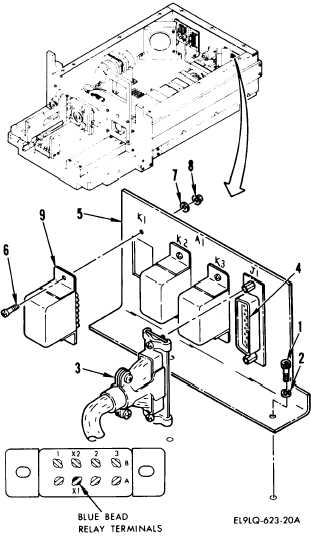
4. RELAY BRACKET ASSEMBLY A1, K1
THROUGH K3 REPLACEMENT
NOTE
This procedure is used to replace K1,
K2, or K3.
K1 is shown.
REMOVAL
a.
Remove OSG covers (1 above).
b.
Remove two screws (1) and washers
(2).
c.
Disconnect connector W1P1 (3)
from A1J1 (4).
d.
Locate defective relay K1, K2, or
K3 on relay assembly (5).
e.
Remove two screws (6), washers
(7), and nuts (8).
f.
Tag and unsolder wires from relay
(9).
INSTALLATION
g.
Install replacement relay in
reverse order of removal.
Refer
to wire list below:
RELAY ASSEMBLY A1
FROM
TO
K1-A1
K1-A1
K2-A1
K3-A1
K1-A2
K1-B1
K1-B1
K1-B2
K1-X2
K1-X1
K2-X1
K2-A1
J1-20
K3-A1
J1-7
J1-19
J1-17
K2-B1
J1-16
J1-9
J1-8
K3-X1
END OF TASK
FROM
TO
K2-X1
K1-X1
K2-A2
K2-B2
K2-B1
K2-B2
K2-X2
K3-A2
K3-B1
K3-B2
K3-X2
J1-10
K2-X1
J1-18
J1-4
K3-B1
J1-15
J1-5
K1-A2
J1-14
J1-3
J1-1
Change 6
5-141
(5-142 thru 5-149 deleted)