TM 11-6625-3081-23
5-27.
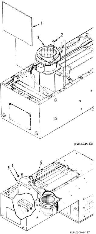
HARNESS ASSEMBLY REPAIR (cont)
5-27
2.
CONNECTOR A1P1 OR A1P2 REPLACEMENT
NOTE
This procedure can be used to replace
connector A1P1 or A1P2.
REMOVAL
a.
Remove bottom assembly cover
(para 5-26 task 1).
b.
Remove CCA A5 (1) using card
extractor.
c.
Remove fan assembly (3) by
removing four screws (2) and
lifting from housing.
d.
Disconnect faulty connector by
loosening two screwlocks (4).
Connector
Mating Connector
A1P1 (5)
A6J1
A1P2 (6)
A6J2
e.
Remove faulty connector from
wiring harness.
INSTALLATION
f.
Install connector on wiring
harness.
g.
Connect connector to mating
connector and tighten two
screwlocks (4).
Connector
Mating Connector
A1P1 (5)
A6J1
A1P2 (6)
A6J2
Change 9
5-121