TM 11-6625-3081-23
5-26.
INDIRECT VIEW DISPLAY 2A1A3 REPAIR (cont)
5-26
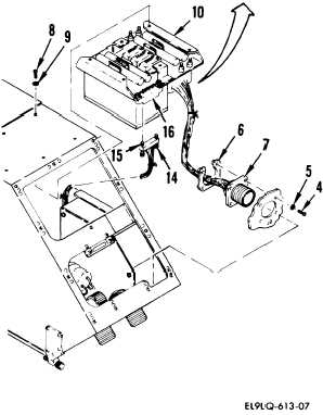
b.
Remove four screws (4), washers
(5), and retainer (6) securing
connector J2 (7) to chassis
assembly.
c.
Remove six screws (8) and washers
(9) securing low voltage power
supply (10) to chassis.
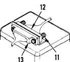
d.
Loosen two screws (11) securing
connector P7 (12) to connector
A12J7 (13). Disconnect
connector P7.
e.
Loosen two screws (14) securing
connector P8 (15) to A12J8 (16).
Disconnect P8 and remove low
voltage power supply assembly.
INSTALLATION
f.
Install in reverse order of
removal.
END OF TASK
5-115