TM 11-6625-3081-23
5-26.
INDIRECT VIEW DISPLAY 2A1A3 REPAIR (cont)
5-26
b.
c.
d.
e.
f.
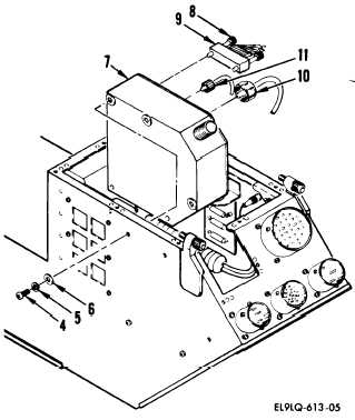
Remove five screws (4), lockwash-
ers (5), and washers (6) securing
high voltage power supply assem-
bly (7) to chassis assembly.
Unscrew and disconnect cable (10)
from connector J1 and lift power
supply to access connector P3.
Loosen two screws (8) on connec-
tor P3 (9) and disconnect from
connector A3J3.
Unscrew and disconnect cable (11)
from connector J2.
Remove high voltage power supply
assembly from chassis assembly.
INSTALLATION
END
5,
g.
Install in reverse order of
removal.
OF TASK
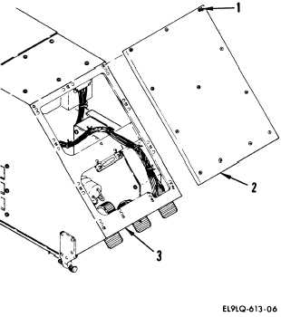
LOW VOLTAGE POWER SUPPLY ASSEMBLY
A12 REPLACEMENT
REMOVAL
a.
Loosen 12 screws (1) securing
rear cover assembly (2) to
chassis assembly (3). Remove
rear cover.
5-114