TM 11-6625-3081-23
5-19. OPTICAL SIGNAL ANALYZER (OSA) RELAY ASSEMBLY 2A1A1A12 REPAIR (cont)
5-19
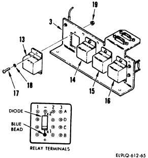
g.
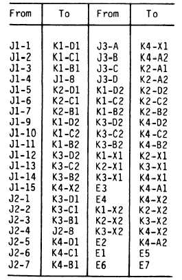
Locate defective relay K1 (13),
K2 (14), K3 (15), or K4 (16).
h.
Tag and remove leads to defective
relay (13).
i.
Remove three screws (17), washers
(18), nuts (19), and relay (13).
INSTALLATION
j.
Install replacement relay (13) on
relay assembly (3) with three
screws (17), washers (18), and
nuts (19).
k.
Install replacement diode on
replacement relay (13) with
banded end of diode to blue relay
terminal.
1.
Place heat shrinkable tubing over
leads and attach leads as tagged
to replacement relay.
5-94