TM 11-6625-3081-23
5-16. OPTICAL SIGNAL ANALYZER POWER SUPPLY ASSEMBLY 2A1A1A6 REPAIR (cont)
5-16
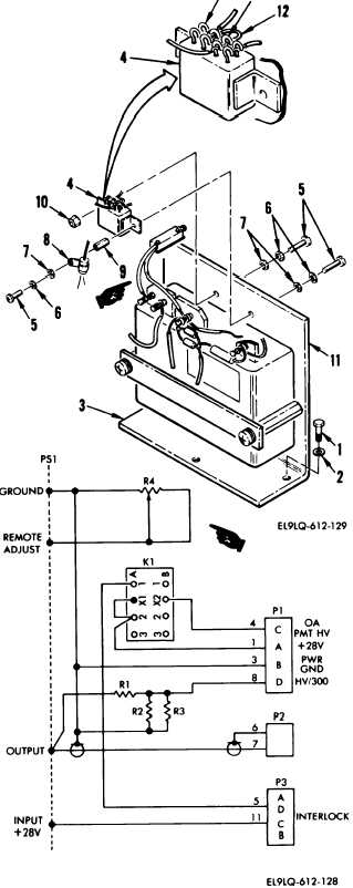
2. RELAY K1 REPLACEMENT
REMOVAL
a.
b.
c.
Remove three screws (1), washers
(2), and power supply assembly
(3).
Place power supply assembly
on workbench.
Tag and remove three leads from
solder hooks on relay K1 (4).
Remove three screws (5), three
lockwashers (6), three washers
(7), clamp (8), standoff (9), nut
(10), and relay K1 (4).
INSTALLATION
d.
e.
f.
9“
END OF
Position replacement relay (4) on
mounting bracket (11) and install
three screws (5), three lock-
washers (6), three. washers (7),
clamp (8), standoff (9), and
nut (10).
Attach jumper lead (12) between
solder hooks K1X1 (13) and
K1A2 (14).
Attach three leads to relay K1
(4) as tagged.
Refer to wiring
diagram.
Position power supply (3) onto
OSA and install three screws (1)
and washers (2).
TASK
Change 1
5-89