TM 11-6625-3081-23
2-38. EXTENDER ASSEMBLY 1A9 REPAIR (cont)
2-38
2. HP-IB EXTENDER 1A9A1 OR 1A9A2
REPLACEMENT
NOTE
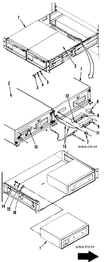
This procedure is used to replace
either extender 1A9A1 (1) or 1A9A2
(2).
REMOVAL
a. on front panel of extender assem-
bly, remove four screws (3),
lockwashers (4), and washers (5),
and pull out extender assembly.
b.
On A1, disconnect the following
connectors:
(1) 115 vac connector (6)
(2) P2 (7) from A1J1
NOTE
Two stacked bus connectors (8 and 9)
connect to 1A9A1 and one stacked bus
connector (10) to 1A9A2.
(3) Loosen two screws (11) and
disconnect top stacked bus
connector (9). Loosen two
screws (12) and disconnect
bottom stacked bus connector
(8).
c.
Disconnect ground lead (13) as
shown.
d.
Remove two screws (14), washers
(15), and brackets (16), and
pull extender straight out.
2-231