TM 11-6625-3081-23
2-38. EXTENDER ASSEMBLY 1A9 REPAIR (cont)
2-38
NOTE
If extender is to be replaced, ground
lead will have to be moved to
replacement unit.
If the same unit
is to be installed, omit steps e
through l and proceed to step m.
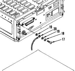
e.
Remove screw (17), lockwasher
(18), washers (19), and ground
lead (20).
INSTALLATION
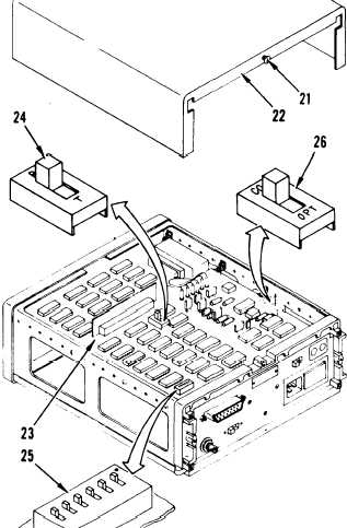
f.
On top cover of replacement
extender, loosen screw (21) and
slide cover (22) off.
g.
On board assembly (23), set the
following switches:
(1) Run/test switch (24) to R
(run).
(2) Address test switch (25),
switches toward black dot.
(3) COAX/OPT switch (26) to
COAX.
h.
Slide top cover on and tighten
screw (21).
2-232