TM 11-6625-3081-23
5-26.
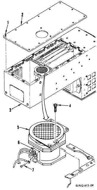
INDIRECT VIEW DISPLAY 2A1A3 REPAIR (cont)
5-26
INSTALLATION
e.
Install in reverse order of
removal.
END OF TASK
7. FAN
REMOVAL
a.
b.
ASSEMBLY A4 REPLACEMENT
Loosen 15 captive screws (1) and
remove bottom cover (2) from
indirect view display (3).
Remove four screws (4) and posi-
tion fan (5) to access terminal
block (6).
NOTE
Terminal block is coated with
silicone rubber that will have to be
scraped off.
c.
On terminal block (6), tag all
leads, remove three screws (7)
and leads, and remove fan
assembly (5).
5-117