TM 11-6625-3081-23
5-13. OPTICAL SIGNAL ANALYZER (OSA) ASSEMBLY 2A1A1 REPAIR (cont)
5-13
22.
2
4 .
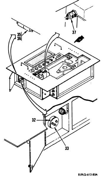
Connect connector W11P3 to connector
W14J1 (37).
Connect connector A6P3 to connector
A1lJ1 (36) and install screw (35).
CAUTION
23 .The photomultiplier tube will be
permanently damaged if exposed to
direct rays of light.
Remove lens tissue from optical open-
ing, carefully install tube carrier
(33) into photomultiplier tube hous-
ing, and install three screws (32).
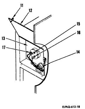
25. On photomultiplier assembly A7 (13),
connect the following connectors:
W11P4 toA7J4 (17)
W16P2 to A7J2 (16)
W11P2 toA7Jl (15)
W9P1 to A7J3 (14)
26. Close photomltiplier access door
(12) and tighten two captive screws
(11).
Change 1
5-65