TM 11-6625-3081-23
2-51. ELECTRONICS DRAWER ASSEMBLY 2A2A7 REPAIR
2-51
This task covers replacement of:
Para
Item
Para
Item
1.
Camera head control unit A3
2.
Circuit card assembly (CCA)
INITIAL SETUP
Personnel Required
Tools
39B ATE Repairer
Conductive wrist strap
Equipment Condition
Conductive workbench mat
Power removed (para 2-24.1)
Materials (appendix C)
Electrostatic shielding bag (Item 7)
1. CAMERA HEAD CONTROL UNIT A3 REPLACE-
MENT
NOTE
Camera head control unit A3 and
internal camera 2A1A2A1A1A15
(paragraph 5-20.1, camera/bracket
assembly replacement) are a matched
set and must be replaced at the same
time.
REMOVAL
a.
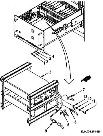
Remove eight screws (1), lock-
washers (2), washers (3), and
pull out electronics drawer
assembly (4).
b. On rear panel of camera head
control unit A3 (5), disconnect
the following cables:
W24P1 from REMOTE SENSOR
INTERFACE A3J1 (6)
W3P3 from OPTOMATION INTERFACE
A3J4 (7)
W2P1 from VIDEO OUT A3J3 (8)
115 vac cord (9)
c.
Remove screw (10), lockwasher
washer (12), and ground lead
(13).
2-280
Change 20