TM 11-6625-3081-23
2-35. PMT CONTROLLER 1A7 REPLACEMENT
2-35
INITIAL SETUP
References
Tools
Goggles
Rubber apron
Materials (appendix C)
Artist brush (Item 8)
Cheesecloth pad (Item 11)
Chemical film (Item 12)
Rubber gloves (Item 26)
Emery paper, 400 grit (Item 35)
Zinc chromate primer (Item 39)
Trichlorotrifluoroethane (Item 48)
Personnel Required
39B ATE Repairer
One assistant
TM 11-6625-3085-12
Equipment Conditions
Power removed (para 2-24.1)
Electronic station positioned for
maintenance (TM 11-6625-3085-12)
Blank panel below PMT controller
removed (para 2-25)
FOLLOWUP
Electronic station positioned for
operation (TM 11-6625-3085-12)
Blank panel installation (para 2-25)
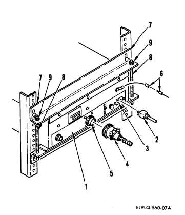
REMOVAL
1. Open left rear cabinet door.
2. On PMT controller (1), disconnect
the following connectors:
115 vac plug (2) from receptacle (3)
P1 (4) from 1A7J1 (5)
3. Disconnect ground lead (6).
NOTE
Top bracket (7) needs to be loosened,
but not removed, to allow PMT con-
troller removal clearance.
4. On each stud (8), loosen top nut (9),
approximately five turns counter-
clockwise.
2-224
Change 2