TM 11-6625-3081-23
5-6. BASE ASSEMBLY REPAIR (cont)
5-6
a.
To replace isolator number 1,
proceed as follows:
REMOVAL
(1) Refer to 1 above and remove
front, rear, and right side
protective skirts.
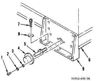
(2) On right side of base remove
four screws (1), lockwashers
(2), washers (3), and two
protective cups (4).
(3) Remove two studs (5) from
base assembly (6).
NOTE
Transport retainers on left side of
base must be in operational mode.
(4) Remove six screws (7),
washers (8), and remove
two transport retainer
brackets (9).
5-11