TM 11-6625-3081-23
5-23. MICROCIRCUIT AND HEAT SINK ASSEMBLY 2A1A2W55 REPLACEMENT
5-23
INITIAL SETUP
FOLLOUUP
Materials (appendix C)
Inner module upper rear access plate
installation (para 2-41)
Cardboard (Item 10)
Rear cover installation
Lacing tape (Item 44)
(para 2-41)
Personnel Required
39B ATE Repairer
Equipment Conditions
Cabinet rear panel removed
(para 2-41)
Inner module upper rear access plate
removed (para 2-41)
REMOVAL
CAUTION
Exercise special care when working
near optical surfaces.
Avoid touch-
ing or contaminating any optical
surface in lower portion of inner
module.
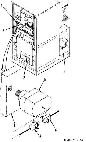
1.
Place cardboard over openings (1) to
protect mirrors (2) from falling
objects.
2.
Cut lacing tape that secures connec-
tor J1 (3) to connector P12 (4).
Disconnect the connectors.
3.
Unscrew and remove microcircuit and
heat sink assembly (5) from inner
left side of camera/target support
assembly (6).
INSTALLATION
END OF TASK
4.
Install in reverse order of removal.
5-106
Change 2