TM 11-6625-3081-23
5-22.
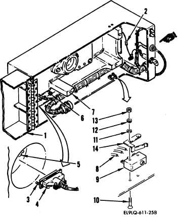
LASER COVER ASSEMBLY 2A1A2A19 REPAIR (cont)
5-22
2. SWITCH S2 REPLACEMENT
REMOVAL
a.
b.
c.
d.
e.
Open cover (1) and separate quick
disconnect splice (2) in chassis
ground lead.
Loosen two screws (3) securing
connector P2 (4) to connector
J16 (5).
Separate connectors.
Remove 16 screws (6) securing
cover assembly to inner module
(7). Remove cover assembly and
place on work bench.
Remove two screws (10), washers
(11), lockwashers (12), and nuts
(13) securing switch S2 (9) and
switch lever (14) to cover.
Remove switch and switch lever.
Tag and unsolder three wires (8)
from interlock switch S2 (9).
INSTALLATION
f.
Install in reverse order of
removal.
END OF TASK
Change 1
5-103