TM 11-6625-3081-23
5-15. OPTICAL SIGNAL ANALYZER PHOTOMULTIPLIER AND BRACKET ASSEMBLY
5-15
2A1A1A7 REPAIR (cont)
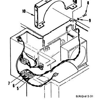
c.
Cut lacing tape and disconnect
the following connectors:
A1P3 from W14J6 (5)
A1P2 from W14J5 (6)
A1P1 from W14J4 (7)
d. Remove six screws (8), washers
(9), and shutter housing
assembly (10).
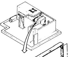
e.
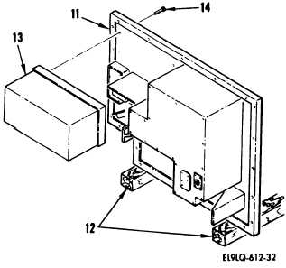
Carefully tilt OSA mounting plate
assembly (11) up on wood supports
(12) to a vertical position.
f.
Using an assistant to support
mounting plate assembly and
photomultiplier and bracket
assembly (13), remove 12 screws
(14).
Note eight short screws
are located in recessed areas of
plate assembly (13).
NOTE
Photomultiplier and bracket assembly
fit on two guide pins. Difficulty
may be encountered while removing
assembly.
g.
Remove photomultiplier and
bracket assembly (13) and place
on workbench.
5-74