TM 11-6625-3081-23
5-14.
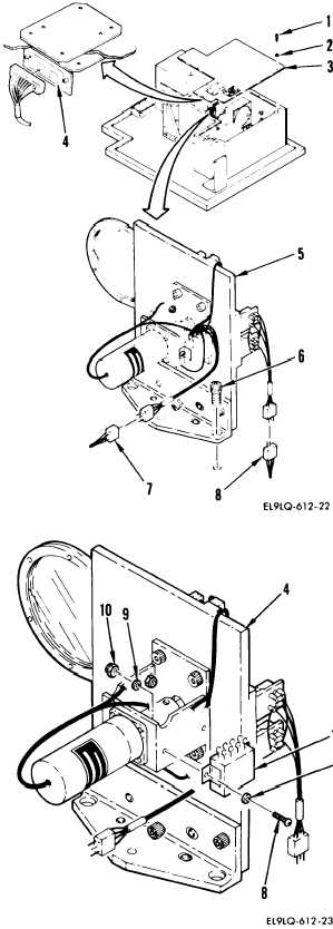
OPTICAL SIGNAL ANALYZER FILTER AND DETECTOR ASSEMBLY 2A1A1A14
5-14
REPAIR (cont)
d.
Cut lacing tape and disconnect
the following connectors:
A14 P1 from W14 J3 (7)
A14 P2 from W14 J2 (8)
e.
Remove filter and detector
assembly (4) and place on
workbench.
f.
Remove two screws (8), four
washers (9), two nuts (10), and
relay K1 (11).
g.
Tag and remove all leads from
J-hooks.
INSTALLATION
h.
Install in reverse order of
removal.
END OF TASK
5-69