TM 11-6625-3081-23
5-25.
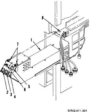
INDIRECT VIEW DISPLAY 2A1A3 REPLACEMENT
5-25
INITIAL SETUP
Equipment Conditions
Personnel Required
Power removed (para 2-24.1)
Rear panel removed (para 2-41)
39B ATE Repairer
FOLLOWUP
Rear panel installation
(para 2-41)
REMOVAL
1.
Disconnect the following connectors
from the IVD (1):
W37P2 from J2 (2)
W37P3 from J4 (3)
W34P3 from J3 (4)
W37P1 from J1 (5)
W36P2 from J5 (6)
2.
Move cables aside to gain access to
screws (7).
CAUTION
IVD must be supported when loosening
screws to prevent dropping.
3.
Loosen two screws (7) securing IVD to
the IVD adapter assembly (8). Remove
IVD.
INSTALLATION
4.
Install in reverse order of removal.
END OF TASK
-
Change 2
5-109