TM 11-6625-3081-23
5-39. SECONDARY HEAT SOURCE ASSEMBLY 2A3A1A17 REPAIR (cont)
5-39
s.
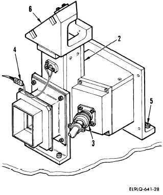
Through shutter opening, position
heat source assembly (2) on
center plate and tighten five
captive screws (5).
t.
Connect the following
connectors:
W5P4 to W23J1 (4)
W5P5 to A17J1 (3)
u.
Install lacing tape as necessary
on cable assemblies.
v.
Hold shutter vanes in open posi-
tion, remove tape, and carefully
close shutter assembly.
END OF TASK
2. MICROCIRCUIT AND HEAT SINK ASSEMBLY
REPLACEMENT
REMQVAL
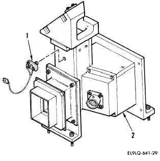
CAUTION
When removing microcircuit and heat
sink assembly ensure cable follows
rotation of heat sink.
a.
Remove microcircuit and heat sink
assembly (1) from heat source
assembly (2). Rotate
counterclockwise to remove.
5-187