TM 11-6625-3081-23
5-38. HEAT SOURCE TARGET ASSEMBLY 2A3A1A1 REPAIR (cont)
5-38
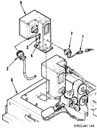
2. HEAT SOURCE A2 ASSEMBLY
REPLACEMENT
REMOVAL
a.
Refer to 1 above and do steps a
through h to gain access to heat
source assembly.
b.
Disconnect the following
connectors:
W6P14 from W25J1 (1)
W6P12 from A1A2J1 (2)
CAUTION
Exercise special care when working
near optical surfaces.
Avoid touch-
ing or contaminating any optical
surface.
c.
d.
Remove four screws (3), washers
(4), and heat source assembly (5)
from target mounting base
assembly (6).
Remove microcircuit and heat sink
assembly (7) from heat source
assembly (5) by turning
counterclockwise.
5-173