TM 11-6625-3081-23
5-34. ELECTRONICS DRAWER ASSEMBLY 2A2A7 REPAIR
5-34
This task covers replacement of:
Para
Item
Para
Item
1.
Relay 2A2A7A4K1 through K15
3.
Heat sink 2A2A7A5 component
2.
Video signal generator (VSG)
4.
Resistor 2A2A7R1
assembly 2A2A7A1
INITIAL SETUP
Equipment Condition
Personnel Required
Power removed (para 2-24.1)
39B ATE Repairer
1. RELAY 2A2A7A4K1 THROUGH
K15 REPLACEMENT
NOTE
This procedure is used to replace
any of 15 relays K1 through K15.
REMOVAL
a.
b.
c.
d.
5-152
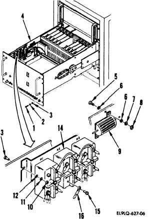
Remove eight screws (1), lock-
washers (2), washers (3), and
pull out electronics drawer
assembly (4).
Remove two screws (5), four
washers (6), lockwashers (7), two
nuts (8), and resistor R1 (9).
Loosen two front and remove two
rear nuts (10), lockwashers (11),
washers (12), and screws (13) and
pull out relay panel to gain
access to relay nuts.
To remove any defective relay
(14), tag and remove four
terminal screws (15) and
wires (16).
Change 2
1