TM 11-6625-3081-23
5-15. OPTICAL SIGNAL ANALYZER PHOTOMULTIPLIER AND BRACKET ASSEMBLY
5-15
2A1A1A7 REPAIR (cont)
4. RESISTORS R1 THROUGH R4 REPLACEMENT
NOTE
This procedure is used to replace
any of four resistors.
REMOVAL
a.
Refer to 1 above and do steps a
through i to remove photomulti-
plier assembly and shutter cover.
b.
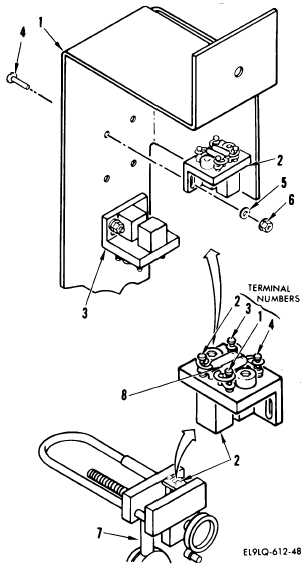
On shutter cover (1), mark loca-
tion of switch (2 or 3) by mark-
ing a pencil line around edge of
switch on shutter cover.
c.
Remove two screws (4), washers
(5), nuts (6), and switch
(2 or 3).
d.
Place switch (2 or 3) in holding
fixture (7).
e.
Remove leads to access defective
resistor (8).
f.
Remove leads of defective
resistor (8).
INSTALLATION
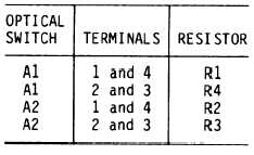
g.
Refer to list below and install
replacement resistor in reverse
order of removal.
h.
Refer to 1 above and do steps n
through v.
END OF TASK
5-84