TM 11-6625-3081-23
5-13. OPTICAL SIGNAL ANALYZER (OSA) ASSEMBLY 2A1A1 REPAIR (cont)
5-13
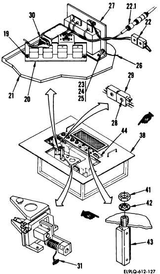
27. Connect the following connectors:
W11J4 to A4P1 (31)
W11P1 to A8J1 (30)
28. Connect connector W11P5 to connector
A5J1 (29) and install screw (28).
29. Attach ground lead (26) to power
supply (27) with screw (23), washer
(24), and nut (25).
29.1 Secure A6R4 (43) to OSA housing
assembly (38) front panel (44) with
locknut (41) and washer (42).
30. Connect connector W11J1 to connector
A6P1 (22).
Secure with lacing tape.
30.1 Connect connector W16P1 to connector
A6P2 (22.1).
31. Position relay assembly (20) onto
mounting plate (21) and install two
screws (19).
5-66
Change 1
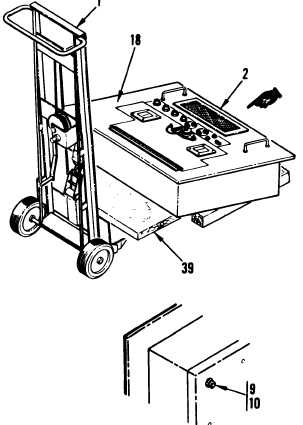
32. Close access door (18).
33. Install four corner screws (9) and
washers (10).
34. Using two persons, lift bottom end of
OSA (2), and roll chassis lift (1)
under OSA.
Lock wheels on chassis
lift.