TM 11-6625-3081-23
5-6. BASE ASSEMBLY REPAIR (cont)
5-6
(15) Apply sealing compound to
threads of screws (8).
Install valve assembly (14)
with four screws (8).
Torque screws (8) to
14 ft-lb.
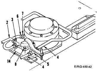
(16) Refer to diagram below and
attach two natural tubes (4)
to tee fitting (5) and yel-
low tube (2) to opposite tee
fitting (3). Finger
tighten only.
(17) Attach yellow tube (6) to
isolator fitting (7)0
Finger tighten only.
(18) Refer to 2a above and do
steps 32 thru 39.
(19) Refer 1 above and install
protective skirts.
(20) Refer to paragraph 5-7 and
adjust base assembly.
END OF TASK
c.
To replace valve number 3,
proceed as follows:
REMOVAL
(1) Refer to 1 above and remove
front, rear, and left side
protective skirts.
(2) Refer to 2C above and do
steps 2 thru 10.
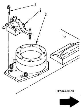
(3) Remove four screws (1) and
valve assembly (2) from
isolator (3).
5-36