TM 11-6625-3081-23
2-53. EXTENDER ASSEMBLY 2A2A8 REPAIR (cont)
2-53
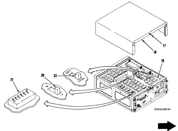
INSTALLATION
e.
On top cover of replacement
extender, loosen screw (17) and
slide cover (18) off.
f.
On board assembly (19), set the
following switches:
(1) Run/test switch (20) to R
(run).
(2) Address test switch (21)
switches down towards black
dot.
(3) COAX/(PT switch (22) to
COAX.
g.
Slide top cover on and tighten
screw (17).
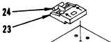
NOTE
The foot pads are not used when the
extender is installed.
They should
be shifted from the replacement unit
to the failed unit.
h.
On each of four foot pads (23),
lift tab (24), slide foot Pad in
direction of arrow, and lift off.
i.
Install foot pads on failed
extender.
2-286