TM 11-6625-3081-23
2-41.1 RADIOMETER ASSEMBLY 2A1A2A3 REPLACEMENT (cont)
2-41.1
CAUTION
3.
4.
5.
6.
7.
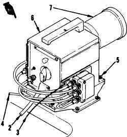
Grasp radiometer firmly while remov-
ing mounting screws to prevent it
from falling into optics cavity.
Remove four capscrews (5).
Rotate radiometer (6) so narrow beam
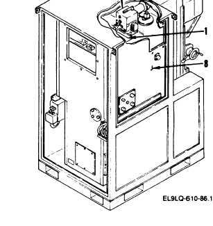
adapter (7) is facing side panel
(8) .
Rotate narrow beam adapter counter-
clockwise and remove from radi-
ometer.
Remove radiometer through side
panel.
Replace narrow beam adapter onto
radiometer.
Rotate it clockwise
until snug.
INSTALLATION
8.
9.
END
CAUTION
Use special care to prevent
accidental change of attenuation
switch positions during
installation.
Failure to have
attenuation switches set correctly
could cause erroneous test results.
Install radiometer in reverse order
of removal.
Ensure that the external switches
are set to the positions indicated:
Switch
Position
EXTERNAL LOAD RESISTANCE
OPEN
APERATURE MULTIPLIER
10
INDICATOR/SCOPE
SCOPE
OF TASK
Change 16
2-253