TM 11-6625-3081-23
2-32. DC POWER SUPPLY ASSEMBLY 1A4 REPLACEMENT (cont)
2-32
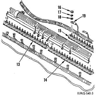
5. Tag wires and remove nut (16), lock-
washers (17), washers (18), and all
wires (19) from terminal boards TB1
(13), TB3 (14), and TB2 (15) as
shown.
5.1 Cut lacing tape as required to free
power supply ground leads from cable
bundle.
Cable/Terminal Board Wire Connection Chart
Wire
No.
1
W5E1
W5E2
2
W5E3
3
W5E4
W5E5
4
W5E6
5
W5E7
W5E8
6
W5E9
7
W5E1O
W5E11
8
W5E12
To
TB1-1
1
1
2
2
3
3
3
4
4
11
11
11
12
12
13
13
13
14
14
Wire
No.
25
28
W24E1
24
27
W24E2
23
26
29
W24E3
17
20
30
W23E3
18
21
W23E2
19
22
W23E1
To
TB2-2
2
2
3
3
3
4
4
4
4
6
6
6
6
7
7
7
8
8
8
Wire
No.
9
W5E13
W5E14
10
W5E15
11
W5E16
W5E17
12
W5E18
13
W5E19
14
W5E20
15
W5E21
16
W5E22
W2E1
Thru
To
TB3-1
1
1
2
2
3
3
3
4
4
11
11
12
12
13
13
14
14
W2E12 Not Used
2-210