TM 11-6625-3081-23
2-30. PROGRAMMABLE POWER SUPPLY ASSEMBLY 1A3 REPLACEMENT (cont)
2-30
4.
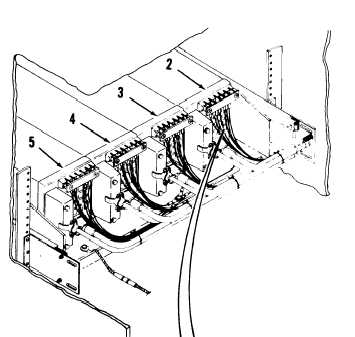
On each power supply (2 thru 5), do
the following steps:
a.
Disconnect 115 vac connector
(12).
b.
Loosen two screws (13) and dis-
connect connector (14).
c.
Remove two terminal board cover
screws (15) and cover (16).
NOTE
Refer to cable/terminal board wire
connection chart for wire location.
Removal of ground wire is not
required.
Cable/Terminal Board
Wire Connection Chart
d.
On terminal board (17), tag wires
e.
and remove screws (18); washers
(19), and wires (20) from each
terminal.
Cut lacing tape as required to
free ground wires from cable.
2-202